
- #ELECTRONIC CIRCUIT DESIGN SOFTWARE PDF#
- #ELECTRONIC CIRCUIT DESIGN SOFTWARE SOFTWARE#
- #ELECTRONIC CIRCUIT DESIGN SOFTWARE FREE#
- #ELECTRONIC CIRCUIT DESIGN SOFTWARE WINDOWS#
#ELECTRONIC CIRCUIT DESIGN SOFTWARE SOFTWARE#
Proteus is one type of circuit designing software and it is a paid tool which is accessible for different platforms like Windows, Linux, & MAC. Please refer to this link to download- Tin圜AD Once the design completed, the file can be saved in. Once the circuit design is finished, the circuit can take print directly, and the user can copy and paste the image in the type of a document, otherwise, user can save them in PNG bitmap otherwise the web format. Additionally, it includes text, shapes, wires, and symbols for confirming the circuit connections. The circuit design can be done using the components namely relays, logic gates, diodes, power sources, capacitor, switches, & microcontrollers. It gives total sign symbol libraries along with tools namely PCB layouts, & schematic capture.
#ELECTRONIC CIRCUIT DESIGN SOFTWARE WINDOWS#
Tin圜AD software is an open source for Windows users. Please refer to this link to download- Zenit PCB Tin圜AD
#ELECTRONIC CIRCUIT DESIGN SOFTWARE PDF#
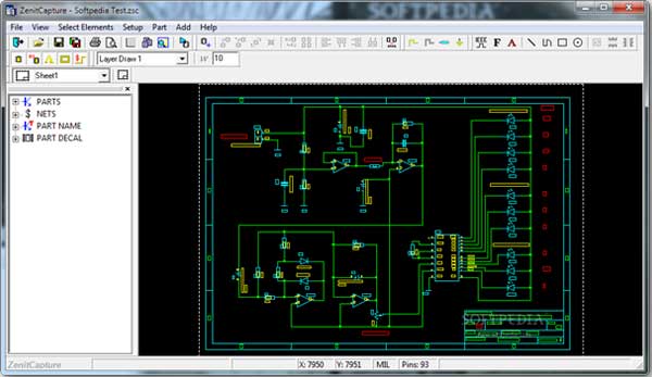
A user guide is also available in PDF format in the help menu. Furthermore, the designing can be exported in the form of TXT which includes the author, design name, number of parts, pins, etc. ZenitPCB software includes a black colored board with a network where every component can be placed with a right click.įinally, the design can be saved in.ZSC format & everyone can also print out a copy of the project. Zenit PCB software is also mainly used for circuit designing using various electronic components for semi-professional projects due to the restriction of usage of 800-pins. Please refer to this link to download- Fritzing Zenit PCB Finally, there is an assistance page to give support in case the consumer faces any complexity during the designing. The design can be viewed in various modes like a breadboard, PCB, and schematic & code. Finally, It also allows the designer to export the design into an image or a PDF. Once the design completes then it saves in.FZZ format. Fritzing is a perfect tool not only for the beginners as well as non-engineers for designing, learning, & sharing the information of circuits.įritzing tools mainly includes different components like switches, resistors, ICs, diodes, gates, wires, junctions, etc. This tool is used to make the Arduino prototypes & PCBs designing. Please refer to this link to download- Logisimįritzing is open source circuit design software and it is used for the Windows users. There is a combinational analysis module that enables the users to take on conversion between circuits, truth tables, and Boolean expressions. There is a module namely combinational analysis, and the main function of this module is to enable the user to take on conversion among truth tables, circuits, &expressions. This software includes many inbuilt components namely logic gates, multiplexer, I/O circuits, Flip-Flops, power, arithmetic circuits, ground. Logisim is very useful in learning on the fundamental logic circuits concepts because it provides an interface like simple to use toolbar.
#ELECTRONIC CIRCUIT DESIGN SOFTWARE FREE#
This is an open source as well as a free tool, and this software is used to design & simulate digital logic circuits. Hence engineers are always looking for alternatives to use. So in today’s EDA tools, there are different features available, but often these tools cost a lot for engineers. It is also very simple to navigate with plenty of options obtainable for best circuit design. So, the circuit design software plays an essential role in electronic engineer’s life for designing & checking the faults in design at usual intervals.

Once the designing part is completed, engineers can utilize their diagram for simulation. The schematic diagram states that how circuit components are connected jointly on a PCB (printed circuit board). While designing electronic projects, circuit designing process is the primary step to make the schematic diagram.


 0 kommentar(er)
